After a bit of good old fashioned arm twisting, I managed to convince an old university friend to use some seriously expensive pieces of kit to peek into the fine detail of the pride of J Allcock and Son’s product line. I sent several samples of our Ambiently-ground FKM crumb, and a competitor’s Cryogenically-ground FKM Crumb to my mate Rob Hooley, studying for a PhD in Materials Science at the University of Leeds, who was kind enough to put them through a Scanning Electron Microscope (SEM) and produce some fantastic pictures.
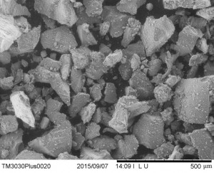
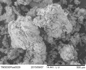
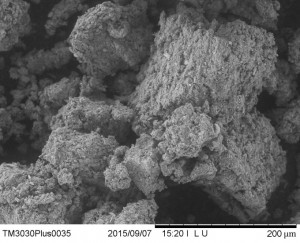
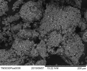
Picture 1 (Left) & 2 (Right): Cryogenically ground FKM 30’s Mesh and Ambient Ground FKM 40’s Mesh
These two pictures above show the difference in surface structure between cryogenically and ambient ground FKM crumb. The Cryogenic material has been frozen and shattered, thus the particle morphology appears much more angular and sharp compared to the torn material, with extremely rough edges due to the physical tearing of the rubber. The coarser material should bond better into a new FKM compound, due to the much larger surface area exposed to the fresh compound, and the possible exposed polymer chains due to the tearing of the material. As cryogenic freezing causes the rubber to break along micro-fissures or micro-tears, the surface would have fewer areas available for bonding.
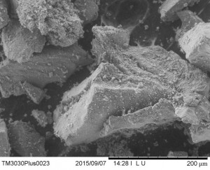
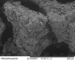
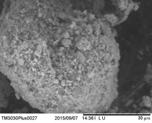
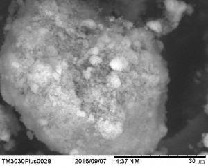
Picture 3 (Left) & 4 (Right): Cryogenically ground FKM 72’s Mesh and Ambient Ground FKM 72’s Mesh
The pictures above again show the two types of ground FKM, but this time the smaller 72’s Mesh size. The size of the 2 grains is very similar, which is to be expected, but again the coarseness of the ambient ground material can still be seen. The scale of the peaks and troughs are not as extreme, but as this is a smaller grain, the increase in ‘bond-able’ surface area is not to be sniffed at. We at J Allcock and Sons believe (and have done many trials that prove our belief) that our ambient ground 72’s mesh FKM binds better than our 40’s mesh FKM crumb. 72’s mesh crumb can therefore be used at higher concentrations in newly made FKM compound, therefore saving you even more on compound cost.
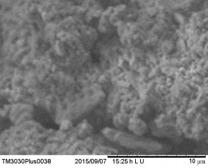
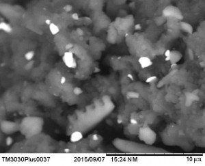
Picture 5 (Left) and 6 (Right). 5 Shows Ambient ground FKM 72 mesh, using ‘LU’ settings, while 6 shows the same material, at the same resolution using ‘NM’ settings.
The ‘LU’ (seen at the base of this picture) indicates a technique that focuses on showing the topography of the sample using secondary electron imaging. SE imaging (SEI) involves electrons produced by ionisation induced by the incoming electron beam. These electrons are very low energy, and as such are very sensitive to the surface structure, this allows for the surface of the sample to be resolved in great detail, even showing the 3 dimensional structure of individual crumb.
Meanwhile, the ‘NM’ (again at the base of the picture) indicates Backscattered electron imaging (BSE), where electrons hit the sample with great energy, allowing them to penetrate the surface and interact with the bulk of the material. This results in the electrons bouncing around the material before being released. The energy they leave the material with is directly proportional to the mass of the atoms they interact with, much like how sound waves are absorbed by a carpeted floor, but bounce off a marble floor. Therefore, the light specks seen in the photo are heavier parts of the rubber compound, mainly Oxides of Magnesium, Calcium and Silicon (Thanks again to some further elemental analysis by Rob Hooley) as the heavier elements reflect more electrons and thus create a brighter image.
Pictures 5 and 6 therefore show the same sample of 72’s Mesh FKM using two types of imaging technique. Picture 5 (like the previous images) shows the surface contours of the FKM crumb, again showing the coarser nature of our material, which is ideal for binding into the compound matrix. Picture 6, however, reveals some of the components of the FKM compound as well as giving a different angle on the depth of some of the troughs and the quality of the FKM compound itself (nice even spread of a moderate amount of fillers can be seen in the crumb itself).
Picture 7 (Top left) and 8 (Top right). 7 shows cryogenically ground 72 Mesh FKM Crumb using LU (SEI) Settings, while 8 shows the same material under NM (BSE) Settings. Pictures 9 (bottom left) and picture 10 (bottom right) show ambient ground 72’s mesh FKM at the limits of the SEM’s resolution, again using ‘LU’ and ‘NM’ techniques respectively
These final images push the resolution of this electron microscope to its limits, with a scale of 10 microns seen in the bottom right hand corners of the lower two images. At such a large magnification, the difference in the surfaces of the crumb is more subtle. The main difference that can be seen would be the exposure of the filler. Picture 8 shows the filler underneath the surface, while picture 10 shows the exposed filler at the surface. We believe that the exposed filler will create an increasingly jagged surface, helping bonding into the compound at a smaller scale.
I hope you’ve enjoyed the pictures, and how microscopic differences in FKM crumb can have a large effect on the resultant compound.
Thanks again for the Fantastic Pictures, and some much needed advice on some of the more technical sections of this post to Rob Hooley, Here’s to our next pint in 2016!


